Control and navigation
Degrees of freedom and kinematics: how a robot arm reaches a point
Why most robot arms have six joints, what forward and inverse kinematics mean, and how reach, workspace and singularities affect what an arm can do.
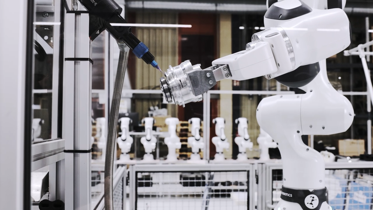
A robot arm is a chain of rigid links connected by motorised joints. How many joints it has, and how they are arranged, decides where the tool can go and how it can point once it gets there.
Degrees of freedom
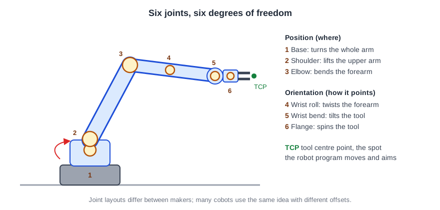
An object floating in space can move in six independent ways: three translations (left–right, forward–back, up–down) and three rotations (roll, pitch, yaw). To place a tool at any position *and* at any angle inside its workspace, an arm therefore needs at least six joints. That is why the six-axis articulated arm is the most common industrial robot.
Fewer or more joints
- Four axes (SCARA): fast arms that move in a horizontal plane plus up and down, with the tool always pointing down. Ideal for pick-and-place and assembly on a table.
- Delta (parallel) robots: three light arms joined at one plate, used for very fast picking from conveyors.
- Cartesian (gantry) robots: straight axes like a 3D printer; simple, precise and easy to make large.
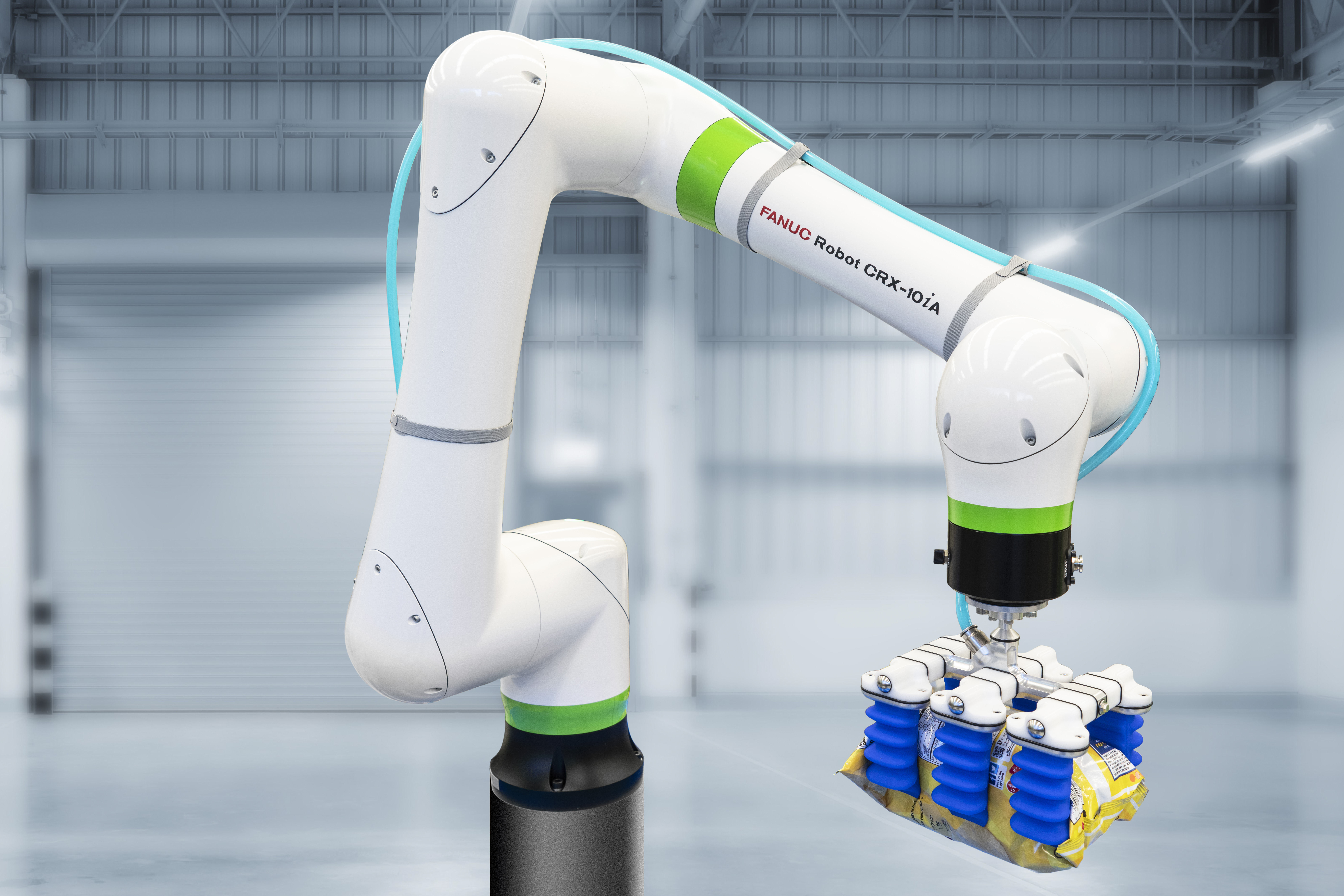
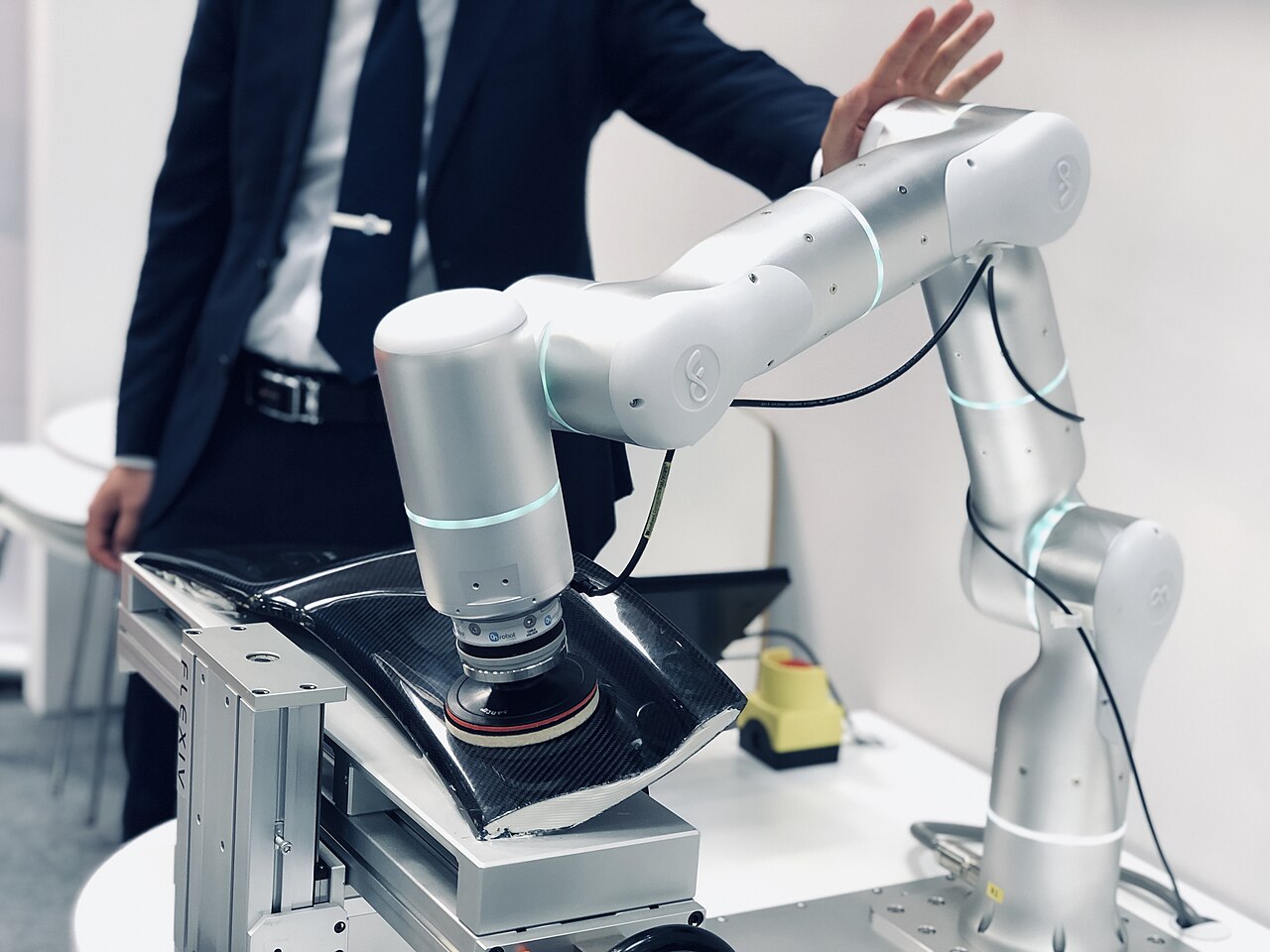
- Seven axes: one more joint than strictly needed. The extra *redundant* joint lets the arm move its elbow while the tool stays still, useful to reach around obstacles or work closer to people, which is why several cobots and research arms have seven joints.
Forward and inverse kinematics
Forward kinematics answers: *if every joint is at this angle, where is the tool?* It has one answer and is quick to compute.
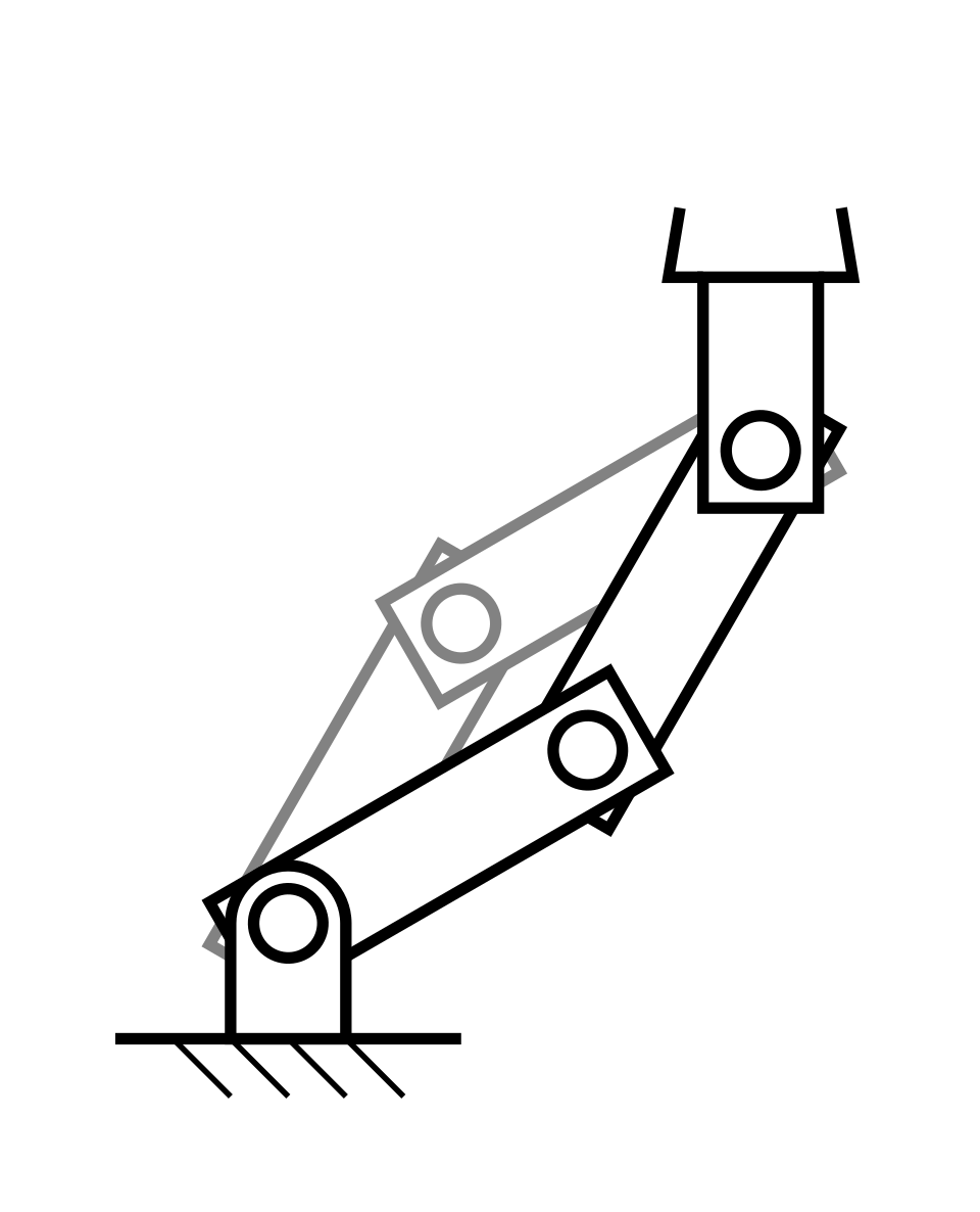
Inverse kinematics answers the question the programmer actually asks: *which joint angles put the tool here, pointing this way?* There may be several answers (elbow up or elbow down, for example), or none if the point is out of reach. The robot controller solves this many times per second while it moves.
Tool centre point (TCP)
Programs don't move joints directly; they move the tool centre point, a point defined on the tool such as the tip of a welding torch or the middle of a gripper's fingers. If the TCP is set up wrong, every taught position will be slightly off, so it is one of the first things to check after changing a tool.
Reach and workspace
The reach in a datasheet is usually the maximum distance from the base axis to the wrist or flange. The real workspace is a thick, roughly spherical shell: the arm cannot reach points very close to its own base, and near the edge of the reach it can only point the tool in a few directions. Payload ratings also depend on how far out the load is.
Singularities
At certain poses two joint axes line up, for example when the wrist is fully straight. The arm then loses the ability to move in one direction, and trying to move through that pose in a straight line can make some joints spin very fast. Controllers detect this and stop or slow down; good programs avoid passing near singularities.
Compare reach of cobots and industrial arms, or read how to read a robot's specifications.